Heating Element Design
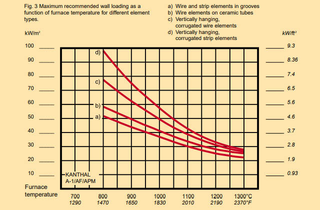
Figure 3 shows the maximum recommendedwall loading for four different element types.Please note that the furnace wall loadingdepends on both element type and elementsurface load. The lower the surface load, thelonger the element life will be. (For descriptionof the element types, see page 7).
When elements are placed on the base of afurnace, special attention must be paid toavoid overheating of the elements. For exam-ple, with a hearth plate having a thermal con-ductivity of ()=1.0 Wm–1K–16.39 Btu in ft–2h–1°F–1and thickness of 15 mm, 0,63 in, at apower concentration on the bottom surface of15 kW/m2, 1.4 kW/ft2, a temperature drop of225°C, 435°Fis obtained through the plate.The total temperature difference between thebase elements and the furnace temperaturewould thus be about 375°C, 700°F. This impo-ses a furnace operating temperature of 1000°C,1830°Feven when using the high-temperatureKANTHAL A-1 alloy, since the element tempe-rature will be about 1375°C, 2500°F.
The example illustrates the significance ofchoosing a hearth plate of a material havinggood thermal conductivity, for example siliconcarbide or heat-resistant steel. Beside measu-ring the temperature in the furnace chamber, itmay also be advisable to measure the tempe-rature of the base elements by means of aseparate thermocouple.
Element surface load
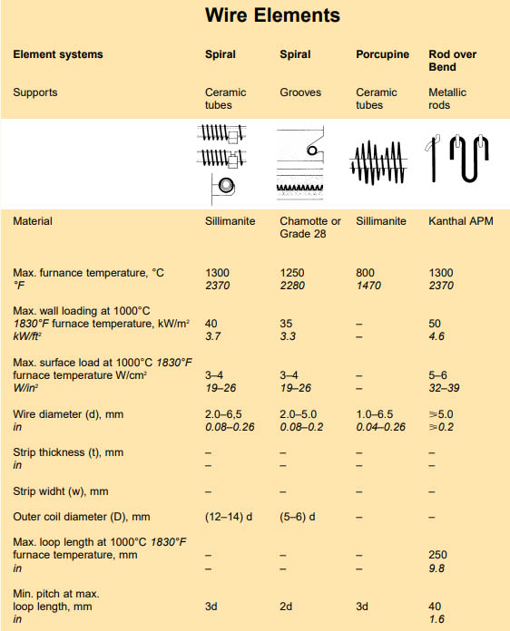
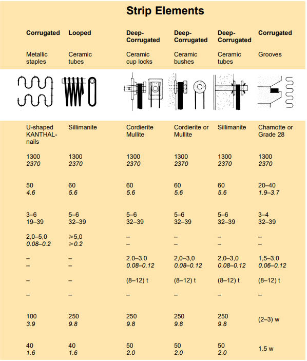
Since KANTHAL alloys can be operated athigher temperatures than NIKROTHAL alloys,a higher surface loading can be achieved wit-hout jeopardizing the life. Element design isalso of great importance. The more freely radi-ating the element form, the higher the maxi-mum surface load. Therefore the R.O.B. (RodOver Bend) type element (corrugated heavywire, mounted on the surface), can be loadedthe highest, followed by the corrugated stripelement.
Spiral elements on ceramic tubes can beloaded higher than spiral elements in grooves.The values in Fig. 4 are given for the follo-wing design conditions:
- Element a Wire and strip element in grooves. Wire diame-ter min. 3 mm, 0.12 in, strip thickness min. 2mm, 0.08 in.
- Element b Wire element on ceramic tubeWire diameter min. 3 mm 0.12 in.
Element types c (strip) andd (heavy wire)
Strip thickness min. 2.5 mm, 0.1 in. Wire diame-ter min. 5 mm, 0.2 in. Pitch min. 50 mm, 2.0 inat maximum loop length and maximum surfaceload.
Maximum recommended loop length:
- <900°C <1650°F300 mm11.8 in
- 1000°C1820°F250 mm9.8 in
- 1100°C2010°F200 mm7.9 in
- 1200°C2190°F150 mm5.9 in
- 1300°C2370°F100 mm3.9 in
For finer wire diameters and smaller strip thick-nesses lower surface loads and shorter looplengths must be chosen to avoid element defor-mation and subsequent shorter element life.
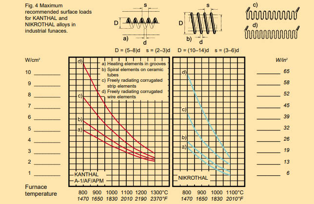
Note:The diagram is valid for thyristor control. For on-off control lower surface loads should be chosen. (About 20%).
Operating life and maximumpermissible temperature
When heated, resistance heating alloys form anoxide layer on their surface, which prevents fur-ther oxidation of the material. To accomplish thisfunction the oxide layer must be dense and resistthe diffusion of gases. It must also be thin andadhere to the metal under temperature fluctua-tions.
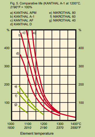
In these respects the oxide formed on KANTHAL alloys is superior to that formed onNIKROTHAL alloys, which contributes to themuch longer operating life of KANTHAL heatingelements. Figure 5 shows the comparative ele-ment life.
Below you will find some general advice on howto obtain as long an element life as possible.
Use KANTHAL Alloys
Heating elements made of KANTHAL alloys have2–4 times longer life than heating elements madeof nickel-chromium material. The higher the tem-perature, the greater the difference.
Avoid temperature fluctuations
The operating life of the heating elements will bereduced by rapid temperature fluctuations. It istherefore advisable to choose an electric controlequipment, which gives as even a temperatureas possible, e.g. thyristors.
Choose thick element material
The material thickness has a direct relationshipto the element life, in that, as the wire diameter isincreased, more alloying element is available persurface unit to form a new oxide. Thus, at giventemperature, thicker wires will give a longer lifethan thinner wires. Accordingly, for strip elements,increased thickness gives a longer life.
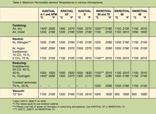
Adjust the element temperatureto the furnace atmosphere
Table 3 shows some common furnace atmos-pheres and their influence on the maximum ope-rating temperature of the heating elements.NIKROTHAL should not be used in furnaceshaving a CO-containing protective gas atmos-phere due to the risk of ”green rot” at 800–950°C1470–1740°F.
In such cases a KANTHAL alloy is recommen-ded, provided the heating elements are pre-oxidized in air at 1050°C 1920°Ffor 7–10 hours.Reoxidation of the heating elements should becarried out at regular intervals.
Avoid corrosion from solid substances, fluids and gases
Impurities in the furnace atmosphere, for instan-ce oil, dust, volatiles or carbon deposits candamage the heating elements.
Sulphur is harmful to all nickel alloys. Chlorinein different forms will attack both KANTHAL andNIKROTHAL alloys. Splashes of molten metal orsalt may also damage the heating elements.
Key Data for Kanthal Elements